ECS Fargate Gateway Deployment Guide
Last modified on November 5, 2024
Overview
AWS Fargate, a serverless compute engine, is a popular option for deploying containerized infrastructure with Amazon Elastic Container Service (ECS). This guide provides step-by-step instructions on how to get StrongDM nodes (gateways and relays) up and running in Fargate.
Our instructions will show you how to set up your environment as shown.
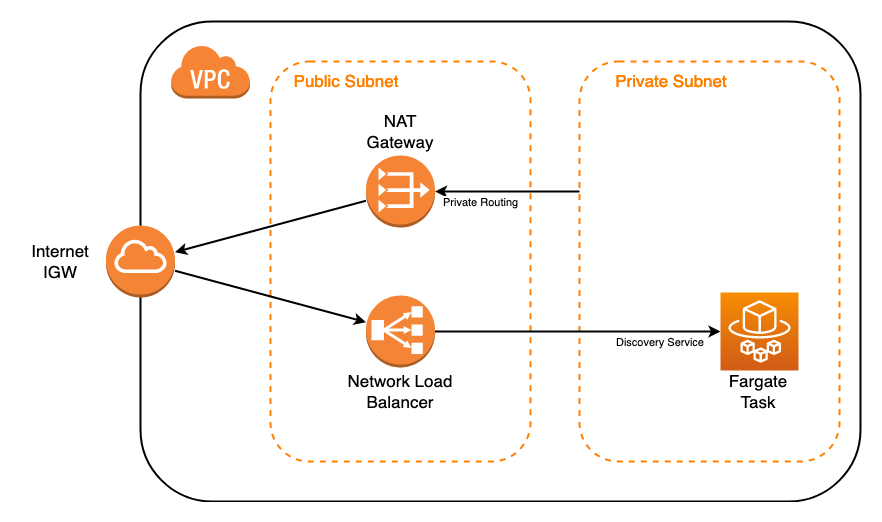
The diagram shows the following essential components needed to deploy a gateway as a Fargate task using ECS:
- Virtual Private Cloud (VPC) with internet gateway
- Private subnet routing traffic through a NAT gateway in a public subnet to connect to the internet
- Network Load Balancer (NLB) distributing incoming traffic from the internet to a Fargate task in the private subnet
Steps
These instructions explain how to configure an NLB, task definition, cluster, task, and service in the EC2 Console, as well as how to generate a token from the StrongDM Admin UI. We recommend that you keep both the EC2 Console and the Admin UI open in your browser so you can easily tab between them.
Create an NLB in the EC2 Console
- Go to the EC2 Console in AWS.
- From the left-hand menu, expand Load Balancing and select Load balancers.
- Click Create Load balancer, and under Network Load Balancer, click Create.
- Set the Basic configuration properties:
- Load Balancer Name: Enter a name for the load balancer.
- Scheme: Select Internet-facing.
- IP address type: Select IPv4. Note that an elastic IP is not required.
- Set the Network mapping:
- VPC: Select the VPC where this ECS gateway will be hosted.
- Mappings: Select the availability zone where you want the load balancer to be hosted (that is, where the public subnet resides).
- Set the Listeners and routing properties:
- Port: Select TCP port 5000. Note that 5000 is the default TCP port specified for SDM gateways, but you can modify it for your environment.
- Create target group: Click the link, which opens a new tab.
- On the Specify group details page that opens:
- Target type: Select IP Addresses as the target group.
- Target group name: Set the name of the target group.
- Port: Set TCP port 5000 for the listener. This port needs to match the port you plan to expose on the Fargate container.
- Click Next.
- On the next page, leave the options blank and click Create target group. Note that a target will be set later once the ECS container is created.
- Go back to the Load Balancers properties page, and click the refresh button next to Target group.
- Select the target group that was just created.
- Click Create load balancer.
- Click View load balancers, and copy the NLB DNS name of the NLB that you just created.
Create a token in StrongDM
To create a gateway token, follow these steps.
- Log in to the Admin UI at app.strongdm.com.
- Go to Networking > Gateways.
- Click Add gateway.
- For Name, enter a name for the gateway.
- For Advertised Host, enter the NLB DNS name that was created in the EC2 Console.
- For Advertised Port, set 5000.
- Click Create gateway. The token appears in a modal. Copy the token and keep it in a secure place.
To create a relay token, follow these steps.
- Log in to the Admin UI at app.strongdm.com.
- Go to Networking > Relays.
- Click Add relay.
- For Name, enter a name for the relay.
- Click Create relay. The token appears in a modal. Copy the token and keep it in a secure place.
Create an ECS task definition
- In the AWS ECS Console, go to Task Definitions and create a new task definition.
- Select Fargate as the launch type compatibility, and click Next step.
- On the Configure task and container definitions page, set the following:
- Task Definition Name: Enter a task name.
- Task Role: Select None.
- Task memory (GB): Select 4GB.
- Task CPU (vCPU): Select 2 vCPU.
- Under Container Definitions, click Add container and then set the following:
- Container name: Enter a name for the container.
- Image: Set
public.ecr.aws/strongdm/relayas the image URL. - Memory Limits (MiB): Set a soft limit of 2048.
- Port mappings: Add a TCP port map to 5000. This port needs to match the BIND port specified for the StrongDM token.
- Environmental Variables: For Key, set
SDM_RELAY_TOKEN. For Value, set the token value created in the Admin UI. Then click Add.
- Back on the Configure task and container definitions page, scroll down and click Create.
Create an ECS cluster
- In the ECS Console, go to the Clusters section and click Create Cluster.
- Services are associated with an ECS cluster. On the Select cluster template page, select Networking Only Powered by AWS Fargate, and click Next step.
- On the Configure cluster page, enter the cluster name, and click Create.
- Click View Cluster, which will open the Clusters Management page.
Create a new ECS service
- On the Clusters Management page, click your cluster name. On that page, click the Services tab and then click Create.
- On the Create Service page that opens, set the following:
- Launch type: Select FARGATE.
- Task Definition: Select the task definition created earlier.
- Service name: Enter a name for this service.
- Number of tasks: Set 1.
- Minimum healthy percent: Set 0.
- Maximum healthy percent: Set 100.
- Deployment type: Set Rolling update.
- Click Next step.
- On the Configure network page, set the following:
- Cluster VPC: Select the Fargate VPC where the cluster is hosted.
- Subnets: Select a private subnet. Without this, the NLB will not be able to reach the container (for example,
10.0.7.0/24).
- For Security Groups, click Edit and do the following:
- Click Create a new security group.
- In Basic details:
- Security group name: Name the group.
- Description: Describe what the group is for.
- VPC: Select the VPC.
- Under Inbound rules:
- Type: Choose Custom TCP.
- Port range: Choose the port (for example, “5000”) you are mapping from the load balancer to the service.
- Source: Choose Anywhere. Please note: The load balancer is only open on the ports you forward, and the service is on a private network. You can, however, specify the IP address or range of the load balancer if you prefer. We recommend starting with an open security group for testing; you can modify it later.
- Click Create security group.
- Auto-assign public IP: Set to DISABLED.
- Load balancer type: Select Network Load Balancer.
- Load balancer name: Select the NLB that you created earlier.
- Click Add to load balancer.
- Production listener port: Select 5000 TCP.
- These steps also enable the Health check grace period field. Scroll up and enter a value of 600 (seconds), for a 10-minute grace period.
- Click Next step.
- On the Set Auto Scaling page:
- Make sure that Auto-scaling is set to Do not adjust the service’s desired count.
- Click Next step.
- Click Create Service.
- Click View Service.
Verify the node
Refresh the page to see that the ECS gateway or relay is online and running. It should take a couple of minutes for the IP address to show up in the target group associated with the NLB, after which the node should appear in the Admin UI with an active heartbeat.
In the Admin UI’s Gateways or Relays page, you’ll see that your ECS gateway or relay is online.
Additional Information
Redundant gateways
We recommend deploying gateways in pairs for redundancy. Gateways automatically load balance and fail over when necessary. Because of this, gateways should not be behind the same load balancer.
Because each gateway requires a unique gateway token, a new Fargate task needs to be defined and associated with a new discovery service. Both services, however, can reside in the same ECS cluster.